
We are living in 21st century where automation of any form i.e. home or industrial plays an important role in human life. When it comes to industrial automation, the concept is applied to large machines or robots which helps in increasing the efficiency in terms of production, energy and time.
Home automation on the other hand involves automating the household environment. This is possible because of the smartphones and internet that we are widely using. Home automation can be again divided in to just controlling the appliances using a smartphone from a remote location and another type filled with sensors and actuators which controls the lighting, temperature, door locks, electronic gadgets, electrical appliances etc. using a “Smart” system.
In this project, we will design a simple home automation project using simple components using which different electrical appliances can switched on or off. The project is based on Arduino and we have used Arduino UNO for the project.
Circuit Diagram
Components
The list of components mentioned here are specifically for controlling 4 different loads.
- Arduino UNO
- HC – 05 Bluetooth Module
- 10 KΩ Resistor
- 20 KΩ Resistor
- 1 KΩ Resistor X 4
- 2N2222 NPN Transistor X 4
- 1N4007 Diode X 4
- 12 V Relay X 4
- Prototyping board (Bread board)
- Connecting wires
- 12 V Power supply
- Smartphone or tablet (Bluetooth enabled)
Component Description
Arduino UNO:
The 8 – bit ATmega 328P microcontroller based Arduino UNO is used in the project to control different components like Bluetooth module and relay network.
Bluetooth Module:
The Bluetooth Module used in this project is HC- 05. As seen in the image below, this Bluetooth module has 4 – pins for VCC (5V), ground, TX and RX.
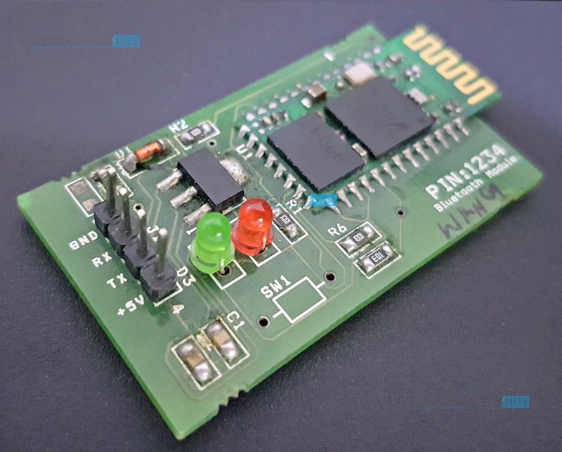
This Bluetooth can be used with Bluetooth enabled phone (or tablet or laptop) and the range of this module is approximately 10 meters.
4 – Channel Relay Board:
A 4 – channel relay board is used in this project to control four different loads. It has all the necessary components and connections like base current limiting resistor, flyback diode, LED indicators and header for connecting it to other devices.
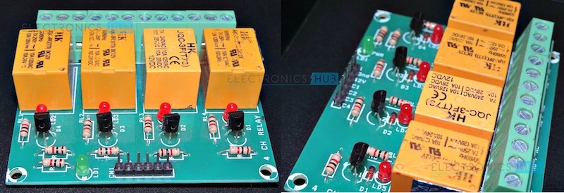
Caution: We should be very careful when using a relay with AC mains.
Circuit Design
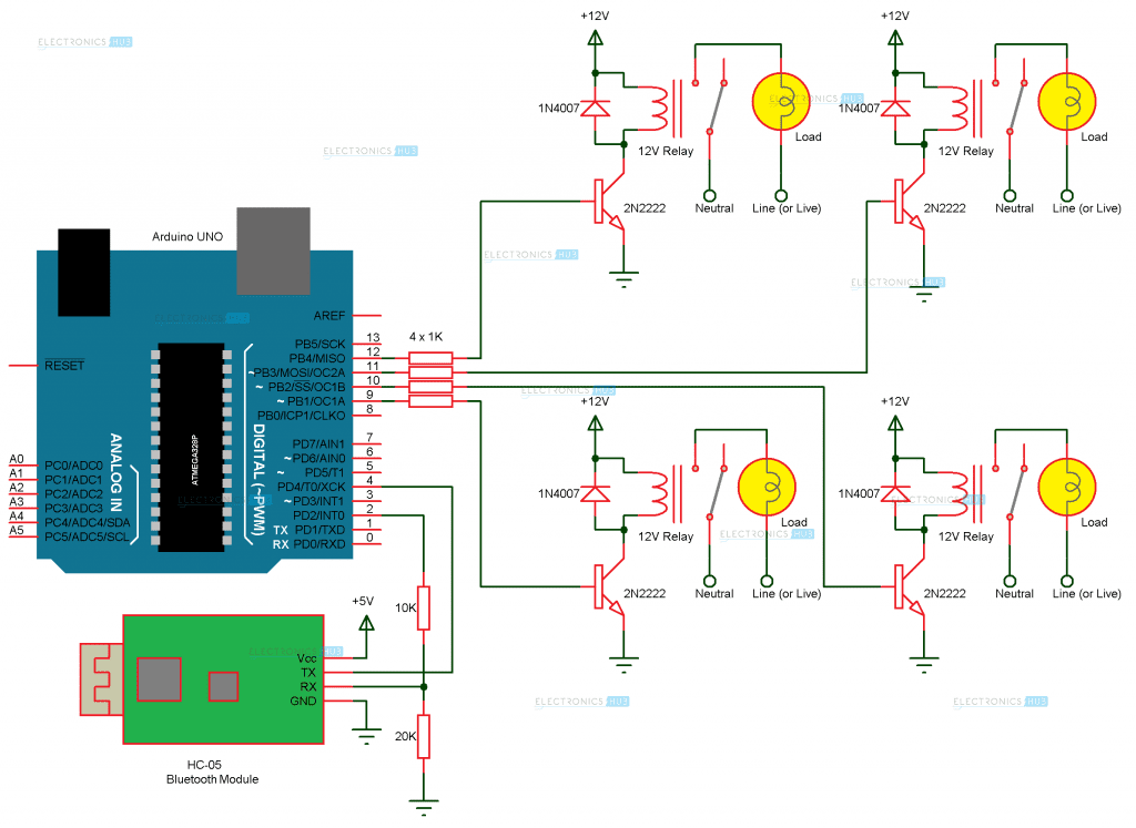
The circuit design of Home Automation based on Arduino and Bluetooth is very simple and is explained below.
The Bluetooth module has 4 – pins: VCC, TX, RX and GND. VCC and GND are connected to 5V and ground from Arduino UNO. The Bluetooth module works on 3.3V and it has an on board 5V to 3.3V regulator.
The TX and RX pins of the Bluetooth module must be connected to RX and TX pins of the Arduino. In Arduino UNO, we are defining pins 2 and 4 as RX and TX using software. Hence, TX of Bluetooth is connected to pin 4 of Arduino.
But when connecting RX of Bluetooth to TX of Arduino (or any microcontroller as a matter of fact), we need to be careful as the pin can tolerate only 3.3V. But the voltage from TX or Arduino will be 5V.
So, a voltage divider network consisting of 10K and 20K resistors are used to reduce the voltage to 3.3V approximately.
Note: Any combination of resistors can be used to bring down the voltage to approximately 3.3V.
The next step is to connect the digital I/O pins of the Arduino to input of the relay board.
More detailed information about Arduino Bluetooth Interface and Arduino Relay Control.
Working Process
A simple home automation project using Arduino UNO, Bluetooth module and a smartphone. The aim of this project is to control different home appliances using a smartphone. The working of the project is explained here.
When the power is turned on, the connection LED on the Bluetooth module starts blinking. We need to start the “Bluetooth Controller” app in our smartphone and get connected to the Bluetooth module. If the pairing is successful, the LED becomes stable.
Now, in the app, we need to set different keys for different loads and their corresponding value that must be transmitted when that key is pressed. The following image shows a set of keys to control 4 loads and an additional key to turn off all the loads.
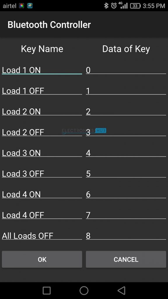
Then we are ready to control the loads. When a key is pressed in the smartphone, the Bluetooth module receives the corresponding data and intern transmits that data to Arduino.
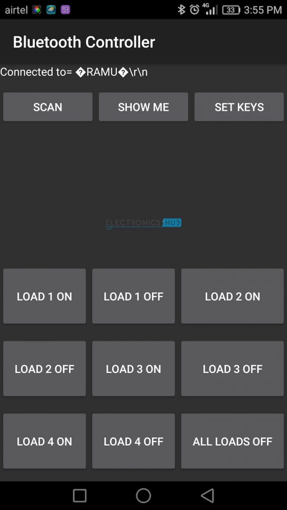
For example, if we press “LOAD 2 ON”, then the data received by the Bluetooth module is “2”.
This data i.e. “2” is transmitted to Arduino. Arduino then compares the received data with the data written in the sketch and accordingly turns on the load 2. The similar action can be applicable to other keys and loads.
Using this type of connection, we can control i.e. turn on or off different home electrical appliances using our smartphones.
Caution: We should be very careful when using a relay with AC mains.
Applications
- Using this project, we can turn on or off appliances remotely i.e. using a phone or tablet.
- The project can be further expanded to a smart home automation system by including some sensors like light sensors, temperature sensors, safety sensors etc. and automatically adjust different parameters like room lighting, air conditioning (room temperature), door locks etc. and transmit the information to our phone.
- Additionally, we can connect to internet and control the home from remote location over internet and also monitor the safety.
Limitations
- The system needs a continuous power supply to be practical or else we might not be able to control the appliances.
- Hence, best way to design the system efficiently would be to implement both the automated control and manual control through switches at a time.
Comments
Post a Comment